
John R. Bentley 2006 - 2017.
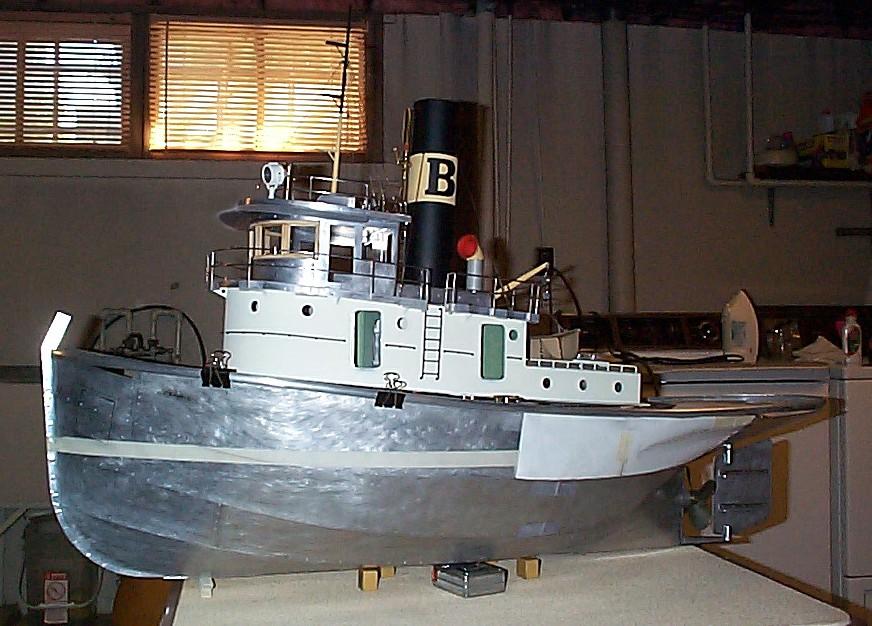
These pages include pictures of my 44-inch aluminum steam tug which began with the steam plant and has been under construction for nearly 30 years. The page started as an addendum to the model tug pages of my old Engineman site, but it will eventually replace that section of the old site.
Considerable work was done to this model in 2017-18. A link at the end of this page shows this on a new page - or you can skip this page and go there directly


The portholes are yet to be glazed. Their design was taken from a photograph of an old New York harbour steam tug. I made a set of stamping dies which forge the frames from annealed aluminum sheet with a substantial clout from a hammer.
This is on the port side looking aft showing berths (still minus bedding and other details).
The hatch perimeters are yet to be surrounded with the smaller bits of the frames.
The lighting was very low here so I didn't have as much depth-of-field as I would like
- I will take this shot properly some day!
The towing bow support is not yet painted - and I notice a loose nut!
I designed this boat to be totally fireproof...the only wood used was the bamboo stern grate and white birch decking boards bonded to the main aluminum deck. I also paneled the inside of the wheelhouse and hung wooden panel wheelhouse doors.
The galley is to the left as you enter this opening.
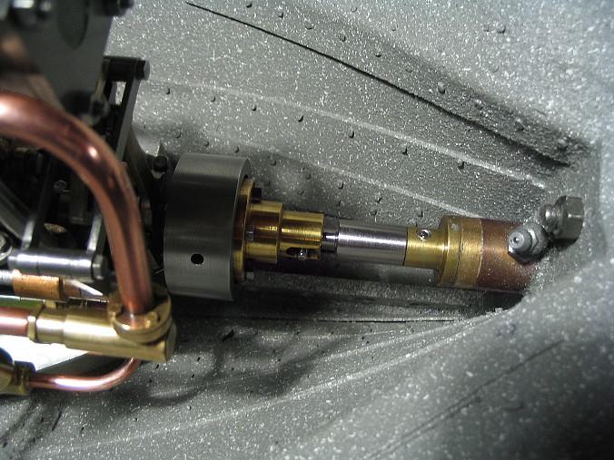
This steam pressure gauge and a grease nipple on the propshaft tube are the only two factory made items on the vessel.
Some of these things are a bit basic, but this will be a working steamship. Turnbuckles, stays and shrouds are the only things holding the funnel and mast to the boat.


Below is a simple comparator that I designed to read water level in the gauge glass. It reads by using two optical fibres and deduces "what to do" with an electric bypass valve on the feed pump. It works by the fact that light is sharply focused when water is present in the glass, while the empty glass tube only attenuates light slightly. Although the circuit works well, the electric bypass valve has never been made.
The deckhouse compartments are made to look ok when peering through open hatches and portholes.
The upper deck will normally be bolted on, preventing these two views from being exposed.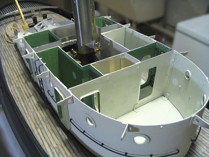

The underside of the main cabin, revealing extensive use of aluminum tape at the joins. This is to prevent any water shipped topside from leaking down into the engine room.
Note the large nuts I made to fasten the main bitts through the wood clad aluminum deck.
The long triangular girder rivited underside in the right hand picture prevents any buckling of the deck when a strain comes on the bitts.

The bitts are aluminum and stainless steel. They have since been heavily coated with rough-surfaced epoxy, mixed with homemade lampblack. I would have no quams about hoisting the entire 60-pound boat by the front and rear bitts.
The towing load applied to the deck assembly through the bitts is transfered to the hull via the big stern deck cleat which is actually a bolt. It is screwed into this "L" bracket pictured below. I wanted plenty of strength in case it was necessary to give a line a sharp pull from shore during testing etc.
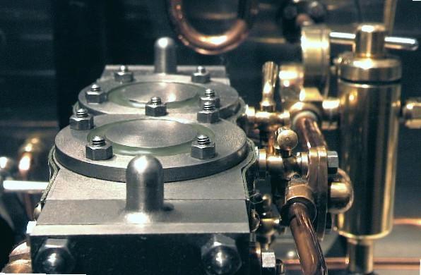
Three pictures showing the machinery arrangement in the hull.

If you would like more detail about these engine room components Click Here

The top rail is black rubber tubing made for car windshield washing systems. I cut a full-length slit with a razor blade. It is inexpensive material and replaceable in a minute. The rubrail is vinyl self-adhesive strip for lining car wheel wells. I also used self-tapping stainless steel screws from behind to ensure a solid mounting.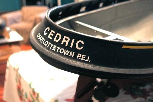
Empty!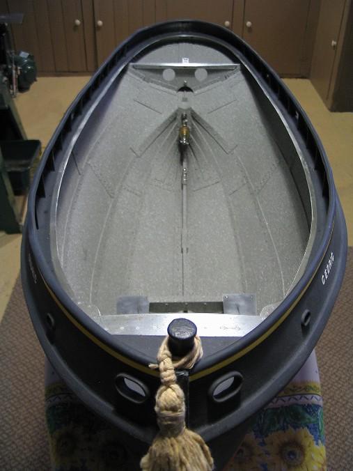


Some views of the hull plating.

Pretty hard to get a compound curve in paper!
Installation of the bulwarks.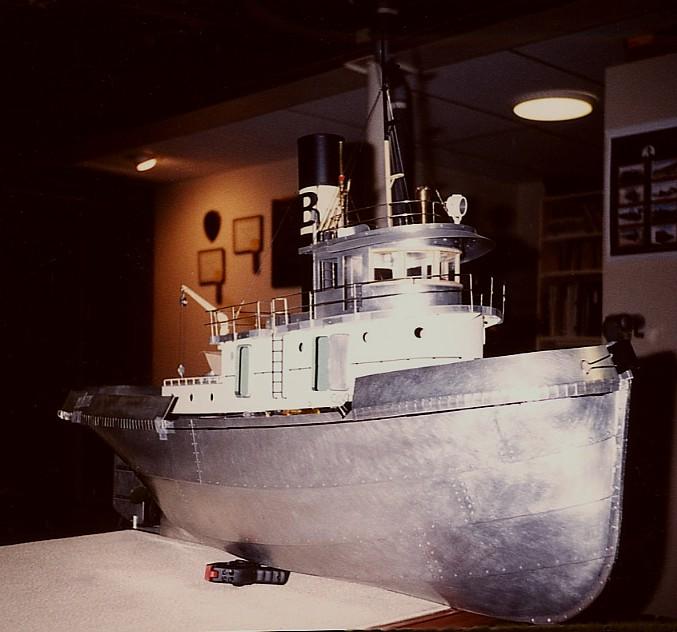
Now here's a rare shot! - the first launch.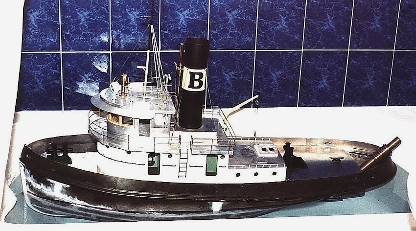
Note that deck planking, bulwark supports, toprail and many details are not yet in evidence. This was an early bouyancy test. At that point in construction, anti-fouling paint had not yet been applied to the bottom, as I wanted to be sure of the predicted waterline location. If you look closely you will notice the line has been crudely applied with a marking pen.
Work remaining on the project: I mentioned that I expected to make paneled wooden doors with windows for the wheelhouse and line the inside of that space with varnished wood veneer. The four main deckhouse hatches and the lifeboat are yet to be made and the railings have not been permanently affixed. The upper deck will be covered with coarse emery cloth and painted.
After that, there is the installation of the controls and some primitive telemetering back to shore, indicating the steam pressure, water level, engine RPM and the condition of the fire. Possible improvements to the existing model are to replace the funnel with a slightly larger diameter version and to remove and replace the boiler with a moderately-operated flash steam boiler plant. (The jury is still out on that last one!)
As mentioned at the top of the page there has been more work done on this boat in 2016-17
- click the first link below this photo:

See recent work on this tug (2016-17)
or
Engine Room
Back to the ModelEngines.info home page