
John R. Bentley 2008.
Tug Engine and Boiler Room
This page contains information about the steam plant installed in my 44-inch aluminum tugboat.
We can start by having a look at the the boiler, since it generates the steam power which drives the engine to propel the tug. It is a Yarrow water tube unit having a top steam drum and two parallel headers (mud drums) on the bottom. A total of 66 water tubes connect the top drum with those on the bottom. The copper end plate of the steam drum is clearly visible and the two small brass plugs on either side of the fire door mark the locations of the front of each of the two mud drums.
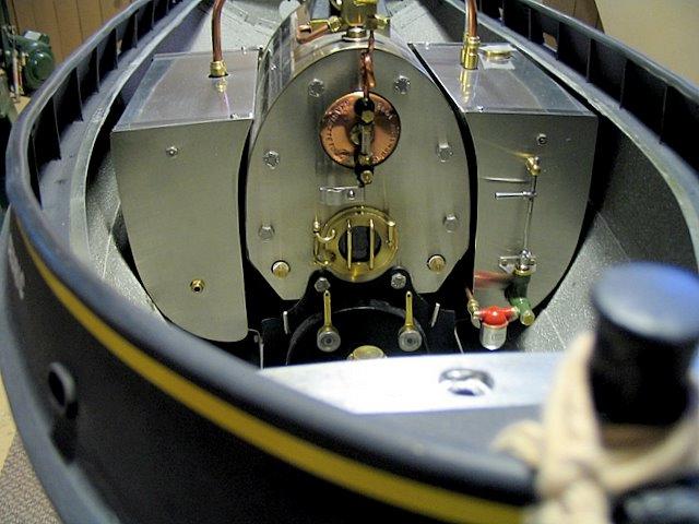
The boiler casing is double, made from two layers of stainless steel sheet separated by an insulating blanket.
The inner casing is of silver-brazed construction while the outer casing is held together by stainless screws.

The coil at the top of this view is the pressure gauge syphon which traps some water to prevent hot steam from damaging the delicate Bourdon tube contained in the instrument. The pressure gauge is out of sight in this shot. The gauge glass water level indicator is clearly visible. A double clamp above the door holds fiber optic cables for remote water level sensing.
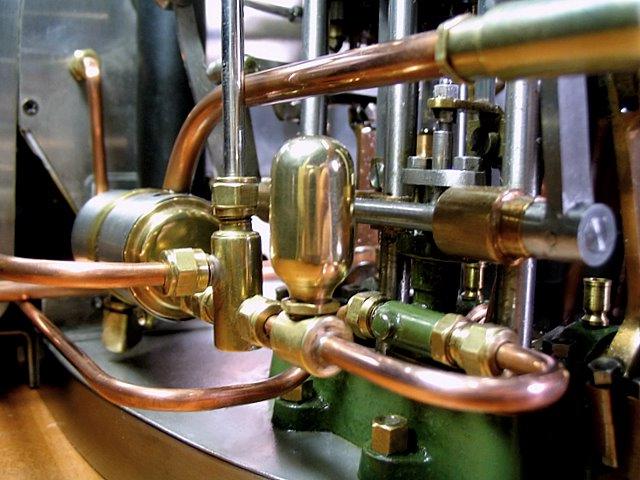
These objects in red and green are the feedwater filter and a hand feed pump for use when first steaming up or when testing the boiler without the engine. During normal operation a crosshead-driven piston pump mounted on the engine supplies the makeup water demand. The filter is a scale copy of a home-heating fuel oil filter containing a stainless steel mesh filter taken from a used burner nozzle.

Here the smokebox door is ajar - it is a good chance to see the left and right mud drum plugs marked "L" and "R".

Here's a look inside the smokebox. There are two layers of tubes on each side - they are staggered so escaping hot gasses flowing between the visible tubes will impinge upon a second set of tubes strategicaly located directly behing each gap.

The decorative swirls on the smokebox backplate are courtesy of my soot cleaning brush.
The black on the lower part of the tubes is caused by shadow, not soot. I was using a small led hand light.
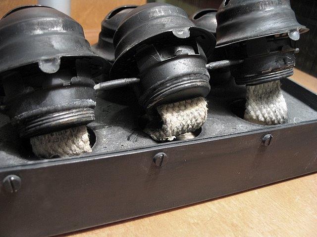
This view shows one bank of kerosene (paraffin) wick burners. In total there are six.

These were made from common kerosene lantern burners
similar to this unused example available everywhere for a low cost
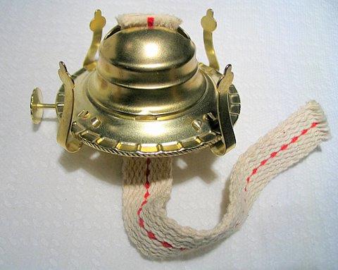
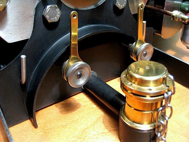
The long brass handles are the ganged wick controls. They can be adjusted by the milled wheels to "agree" with each other for combined remote control. The large brass cap marked "F" is the fuel filler. The small silver rod handle on the left is withdrawn to allow the complete burner / tank assembly to fall clear of the boiler smoke box for maintenance (there's also one on the right).
Removing the one of the two burner assembly hangers
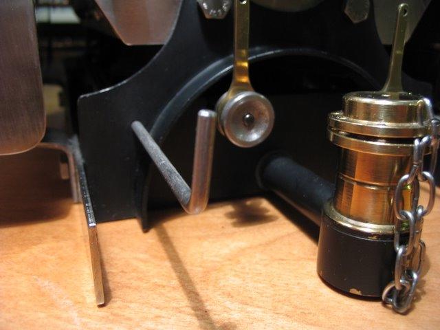
Looking up to the boiler floor from the space vacated by the burners and fuel tank

The complete fire. The tank holds about 0.6L of Kerosene (paraffin).

It will burn for more than an hour and can be refilled while the boiler is operating.
Air enters from beneath through these diffusers then is directed to the
base of each flame by the curved domes with the large slits in the top.

With the induced draft in the smokebox provided by the steam blower,
the fires tend to become very bright, very white and very hot!
Lifting one bank of burners reveals the wicks and the connecting rod for combined wick control.
The crosshead-driven pump and air chamber

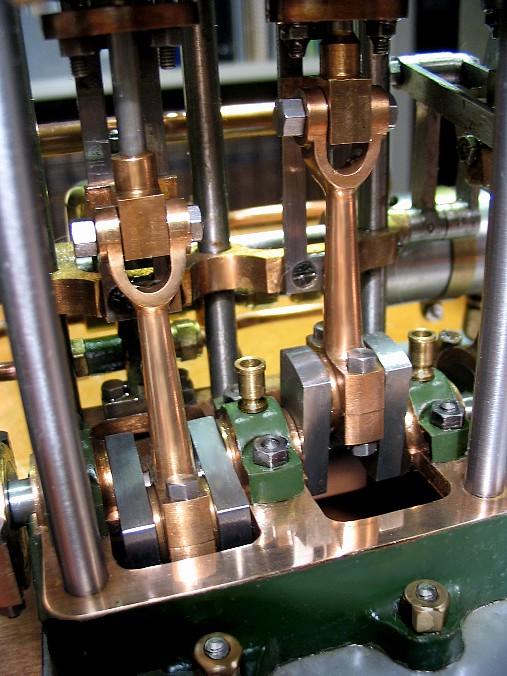
The Engine
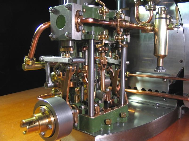
The engine is a double-acting twin with Stephenson's link reversing gear. Power is supplied through 360°. Bore is one inch and the stroke is seven-eighths of an inch.


Back to Page One of the Tugboat
Recent work on this tug
or
Back to the ModelEngines.info home page