
© John R. Bentley 2007.
October 2007.
© John R. Bentley 2007.
I am not making any promises or claims of performance or safety, either in the construction or use of this leadscrew. I am just describing my own system and how I made it. For my requirements, I have been very satisfied with the level of performance it has provided me over the last number of years.
Here are my own (slightly biased!) comments on leadscrews and threading:
I don't feel the use leadscrews and threadcutting are necessarily synonymous. I cut threads so often that changing gears and getting the threads to the proper major / minor diameters might be a job better suited to Superman. The small sizes of most of my threads almost dictate the use of taps and dies. I think that a thread follower is a good way to go with the Taig. I have been able to produce very satisfactory threads on a 35 mm SLR camera filter ring, as well as much coarser threads (in the 10 T.P.I. range). Equivalents to the threads on the Taig spindle are easy to reproduce reasonably accurately with this method. My foray into the world of threadcutting via the standard old-fashioned method of changears / leadscrew on my Asian mini lathe didn't indicate that method is one bit better or easier than using the overhead hob system.
Auto feeding the carriage:
I think that a well thought-out leadscrew addition to the Taig is really worth the effort - just for auto feed. If, down the road, one wishes to power it with a digitally-controlled motor for threading (like the Frog), then that's fine, at least they have something substantial to build on. The installation of a leadscrew for auto feed saves a lot of time (as well as your eyesight) and will produce as good a cut as can be managed by hand, on every pass. I find that just to be able to get up and stretch my legs and gaze out the window during a two-minute pass is a great strain reliever. It also facilitates brushing on coolant steadily when cutting stainless steel, or clearing swarf in other situations if a large mess is forming, or when a fine finish is required.
I wanted to add a leadscrew that met three main criteria:
1) It would require an absolute minimum of cutting or modification to the stock lathe.
2) The leadscrew would be mounted to the lathe itself, not to an add-on base.
3) The completed assembly would in no way interfere with the existing operation of any part of the lathe or accessory.
Your requirements may be quite different from mine, I wanted to be able to easily move the lathe to a new bench location, or transfer all my attachments to a new Taig, should that ever become necessary - but now I don't think it ever will. I already had threadcutting capability on the Taig, so that was not of interest to me.
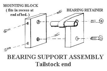
I met my own three requirements completely, except in #3 .... the leadscrew handwheel must be removed (setscrew) in order to slide off the carriage ( or the headstock ). This problem could easily be rectified by a simple "pull-off" system with a flat on the shaft. A crafty friend in London has adopted my system, but with two improvements: he simplified the rear leadscrew bearing support by loosely copying my front one, and he also added a efficient simple in-line disengagement apparatus in the leadscrew shaft, based on the Sherline design. He copied my carriage additions verbatim and sent me a video, showing his leadscrew working perfectly. (His video had sound capability, but he didn't need it - there was no sound!). I have included a sketch of his new tailstock-end bearing support.
It is easy to overlook some obscure function of the lathe and its attachments when adding a leadscrew, but so far I have not found any which have been negated by this addition.
The leadscrew derscribed here is used for auto feed only and not screwcutting. I use taps and dies in the tailstock for nearly all my threading. Special jobs are done on my homemade threading attachment. The leadscrew was made from an ordinary inexpensive 3/8" x 16 T.P.I. threaded rod from a hardware store. I filed the thread under power in the lathe with a 3-corner file to remove the cadmium plating and to smooth the thread form. I have a crude scribbling of the headstock end bearing and gearbox support which I have included below. The gearbox was made up from modified gears taken from a standard electric stove clock.
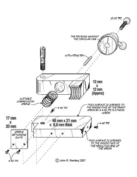
Here is a sketch of the half-nut arrangement in the carriage and some pictures to help interpret the diagram.
Views of the Carriage and Half-Nut
ABOVE: left side view of the carriage apron, showing one lower block mounting screw.
BELOW: Apron bottom showing the half-nut, the retainer plate and the lower block.
The half-nut is exactly that - a hardware-store variety 3/8" x 16 hex nut, sawn in two with a hacksaw. I removed the excess top and bottom material and silver soldered the back of the half-nut to the swing arm.
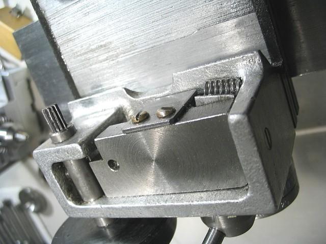
APRON REAR VIEW.
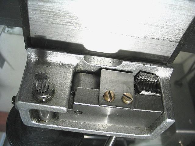
BELOW: View of the half-nut lever in the disengaged position and showing one stop pin.
The "circular cam" mentioned in the diagram was just made from round stock sawn off at an angle, given a flat spot with a file, then parted off. It was then silver soldered into the recess on the half-nut engagement lever's hub.
Pins limit the rotation of the lever, visible in the view on the left and below.
The round nose pin at the top presses against the spring-loaded half nut lever arm inside the carriage apron.
(The other two pins are stops.)
LEADSCREW BRACKET (headstock end).
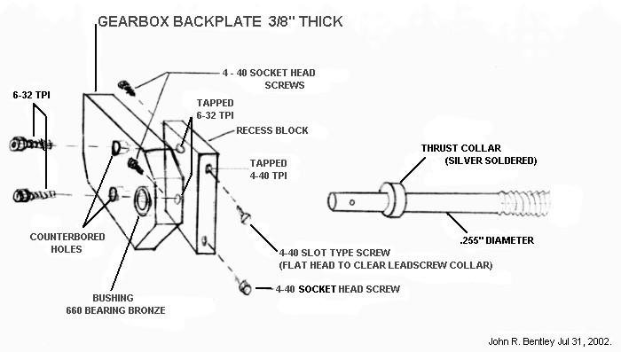
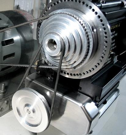
The "gearbox backplate" can hold any kind of gear setup you want to make, buy or steal. Mine was made from electric stove clock gears and has a two-groove pulley, taking an O-ring belt from the Taig's main spindle pulley which is located directly overhead.
As seen above, the gearbox is covered - this shows all that is inside.
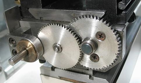
Ratios from spindle to leadscrew of 60:1 and 30:1 for a 16 TPI leadscrew would be nice.
About 30:1 is my own slowest feed, but 60:1 might be handy for very fine finishes.
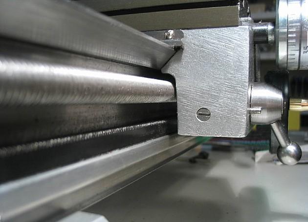
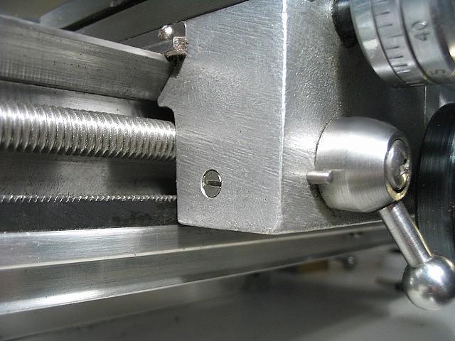
BELOW: the new tail end design.
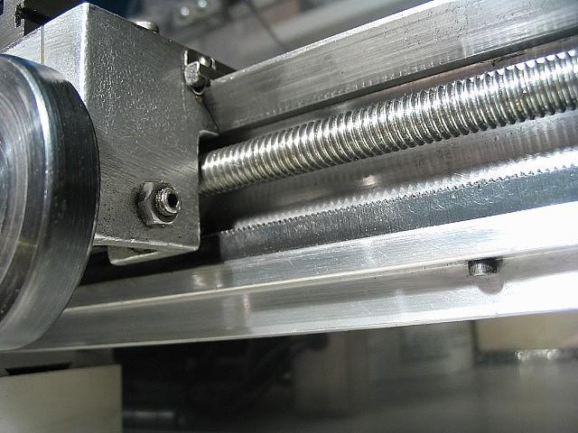
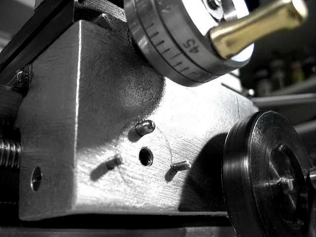
Some idea of the clearance under the headstock can be seen below - the hex key is 5/32".
The leadscrew has been turned down to .255" to give knuckle room when using the carriage stop screw.
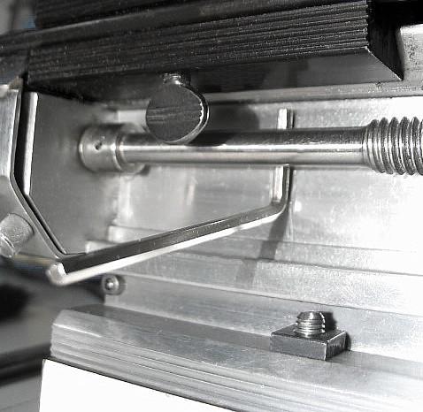
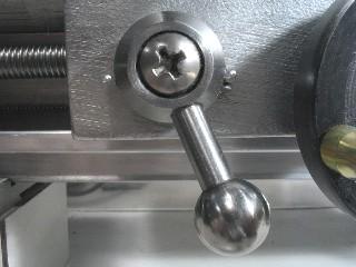
On my new Taig, this is the space where I inserted an inline dog-type clutch to disconnect the leadscrew from the gearbox.
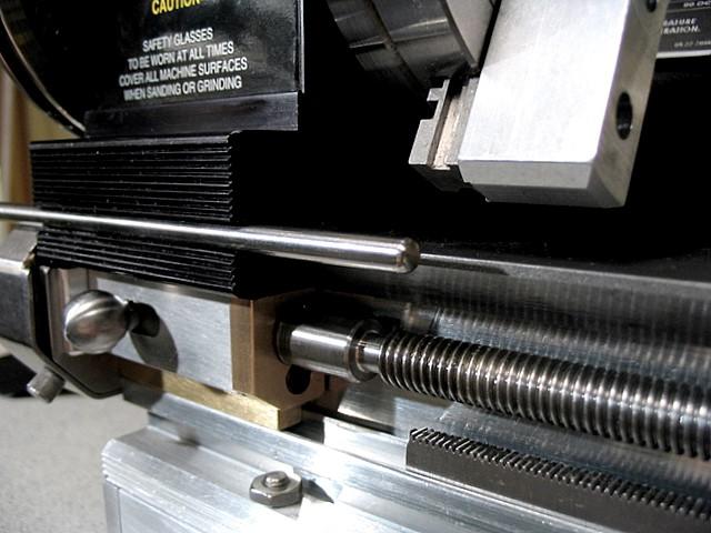
Here's how it looks on the new lathe...
(a knurled carriage stop lock thumbscrew has been added above the rod - not shown in this photo)
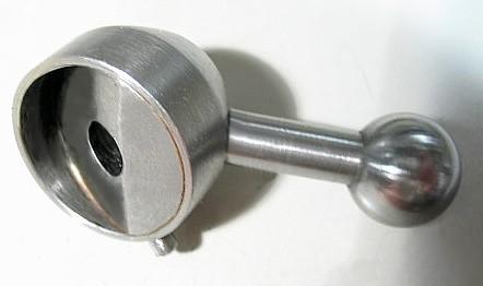
If you want to see pictures of the clutch internals Click Here
Below are a few questions from a Taigtools Yahoo! group member and my answers:
1. The cam lever - how is attached? Is is screwed into the carriage?
Yes, the Phillips head 10-32 screw is screwed into a tapped hole. The hole is in effect a blind hole because the screw seats against the lower block inside the apron. By grinding the screw to the perfect length (or dropping spacers down the hole), it does not bind the lever hub.
2. You indicated that there is pin that pushes the half nut against the leadscrew. What holds the pin in place? Does the pin bear against the face of the cam?
The pin presses against the spring-loaded half-nut arm, and the outer end slides against the face of the cam. I rounded and polished the ends of the pin as perfectly as I could, so it would function smoothly. And it does.
3. In the front view picture, it looks like the pin is poking out next to the lever.
What you are seeing in that picture are the two limit stop pins pressed into holes in the face of the apron and a third pin stuck in the periphery of the engagement lever hub which contacts the appropriate stop pin.
4. How secure is the single half nut? - I wouldn't think you would get much flex in a 3/8 leadscrew over the length of the Taig bed.
It's just dandy! It will create such force that I can't stop the carriage with my hands, yet in a real jam it will just go "clunk, clunk....", as the rod flexes out of the way. This seemed to work out very well with the cheap threaded rod I used. I am very happy with this aspect.
5. Did you have to drill the Taig bed to attach the bearings at each end?
Yes. Originally four tiny holes were drilled in the aluminum bed extrusion very near each end. On my new lathe, I have added a disconnect gadget to the leadscrew and reduced the number of screws to one 4-40 socket head capscrew on each side at the headstock end of the lathe. The screws pass through the aforesaid holes and into tapped holes in the mild steel block which fills the recess at that end of the bed. In the original sketch they are shown as three 4-40 socket head capscrews and one flathead 4-40 to provide clearance for the leadscrew. Obviously, similar Metric or BA screws would be fine.
'Best of luck!
John
Back to the Taig