FLYWHEEL FABRICATION
for the Naval Brass Vertical Engine
© John R. Bentley 2005.
Below: Turning the flywheel hub from used boat propeller shaft material.

Creating a hex section to mount the spokes.

I used a hex fixture in the vice to hold a Taig 4-jaw chuck in the Micro Mill in order to create the hex.
Rough turning the spokes in the Taig lathe. Spokes silver brazed to the hub's hex flats.


Trimming the spoke tips and sides in the Taig lathe.

The flywheel's inner rim is silver brazed around the periphery of the spokes.


Below: The main outer rim is about to be made from these pieces.
(They were rough-hewn from another length of the boat prop shaft.)

A little heat does the trick!


I was a bit shaky when I made the left picture. (My wife was driving the torch!)
The completed rim, with a steel band clamp to prevent un-brazing when the final silver brazing operation permanently mates the hub/spoke unit with the outer rim.


At last! All one piece! Now it's at the same point as a rough casting.

Truing the rim of the wheel between centers on the lathe while it is keyed on to the engine crankshaft.

A little hand-filing on the spoke corners, then it will be ready for sandblasting.

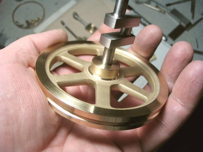
Here is the sandblasted wheel being tried in position prior to final machining and polishing.

The sandblasting was done with one of those $10 kits that appear in the discount hardware stores.
The package included a bottle of grit and a tiny airbrush-style blaster. I taped the rim and hub with ordinary masking tape and used 50 psi of air pressure.
Finished. (I know you have seen this one before - I just included it for reference.)

BACK