John R. Bentley 2006.
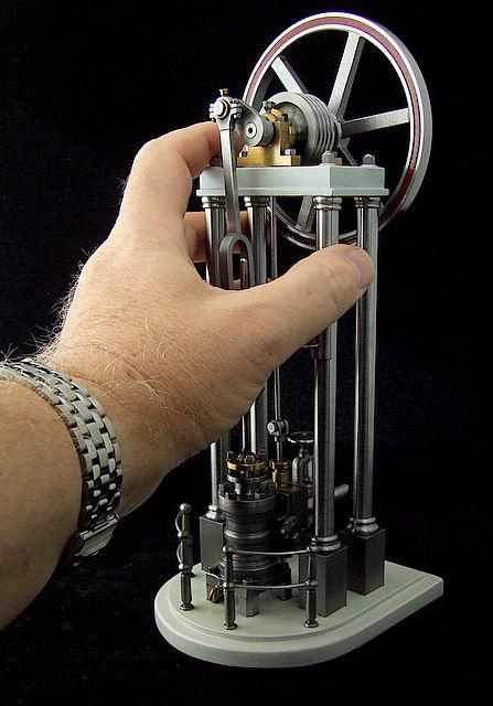
I have included a few old photos of this engine which I hope will show some detail.
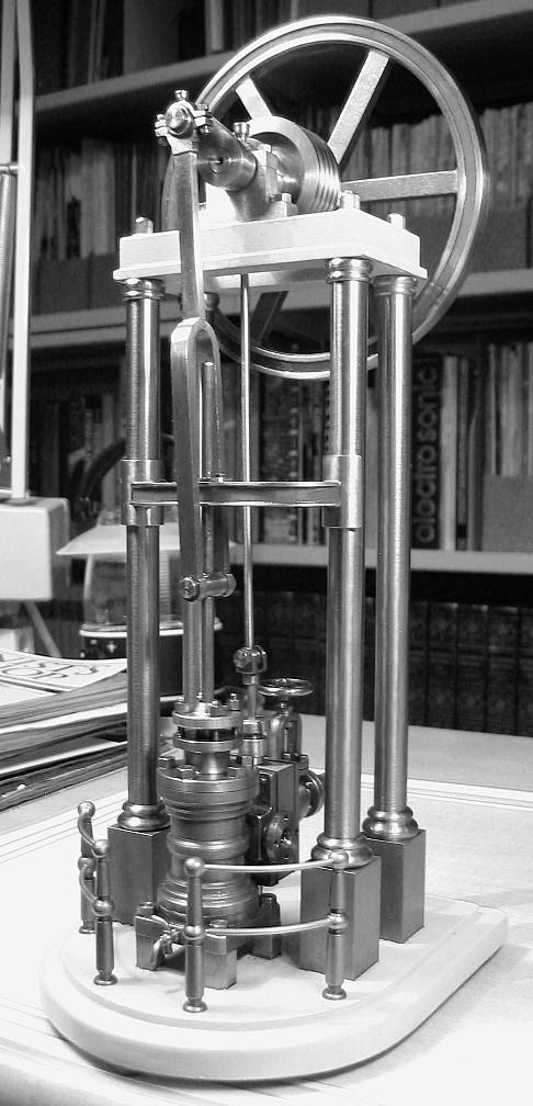
(I just thought this black & white image may reveal some details that are not present in more natural lighting.)
If the general appearance of this engine, especially the entablature, flywheel and other top components look familiar it is not by coincidence. I was in the possession of a Stuart Models catalogue from the early 1980's which had an impressive photo of the Stuart Real which I had admired for years. It was not on my list of realistic purchases as the company only supplied castings but not materials. From my isolated location shipping the castings set and acquiring the materials was not within financial practaciality for me 40 years ago.
What I didn't realize was that the photo gave the engine an elongated appearance and later catalogues showed it in more realistic perspective. It was this long, lanky appearance which initially had apealled to me and by the mid-90's some matereials such as good quality steel keystock and rod became available at reasonable prices here in my area. I decided to try to make it from scratch using the old photo as a rough guide to make a drawing. I wanted it to look the way I liked it so to force the issue before even making a drawing I cut the four columns to length from steel rod.
Okay this gets worse!
My full size drawing was too long to fit on the ordinary 8.5" x 11" graph paper which I had on hand. I made 2 drawings (the engine's lower section with the columns going off the top of the page and the other was of the top of the engine with columns decending off the bottom of the page). Obvbiously my plan was to stick them together with clear tape and partially overlap them by a few inches. Well there of course was the opportunity to test the appearance of different heights. By simply sliding the two drawings with more or less overlap I could make the engine any height within reason. Great! So I added another 1 1/8". Now my previously cut columns were too short. That explains those nice 1/2" square supports below the column bases.
The steam chest and stainless steel stop valve

Another view from the back.
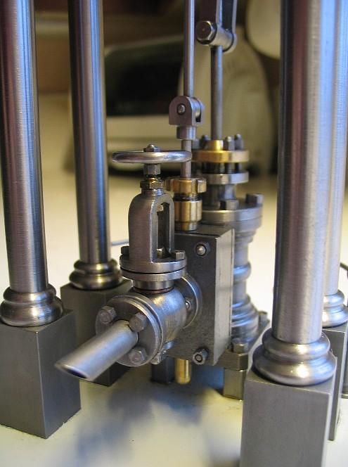
All the stainless steel components (used for the large steam valve, piping & flanges and railings & stanchions) were etched with printed circuit etchant purchased from Radio Shack back in the day. This treatment produces a nice satin lustre similar to that of clear anodized aluminum.

The cylinder and steam chest are cast iron, machined from an old fashioned window weight. Most other parts including the flywheel, most of the base, the entablature, coloumn base supports and curved bracket between the front columns are made from keystock. The brass parts were made from the discarded propeller shaft of a lobster fishing boat.

Here are some measurements that I made of the finished engine:
The plain cylindrical sections of the columns are 5 5/8" x 3/8" diameter.
The little capitals at the top of each column are 3/16" high x 1/2" diameter (at the maximum point).
The round bases are 1/4" high x 5/8" diameter (maximum)
The square column supports are 1 1/8" long x 5/8" x 5/8".
The top of the upper table should be 7 7/8" above the top surface of the main base.
The dimensions of the upper table are actually 1 1/2" x 2 7/8", but the "lip" around the bottom of the table extends outward 1/16" more in all four directions.
The overall height of the table (including that lip) is 1/2".
This all means that the bottom area occupied by the four columns on their bases is 3 3/16" x 1 3/4".
The stroke is 1". I think the bore is 5/8". (the smallest outside diameter of the cylinder is 3/4", so I bored it as large as possible).
The cylinder end covers are 1 1/16" diameter, and the cylinder assembly sits on a square baseplate about 1 1/8" x 1 1/8" x 3/16".
This little baseplate is raised on four legs 3/8" above the main base surface.
The steam chest is 7/8" x 1 1/4".
The top of the bronze bushing on the piston rod guide is 5 1/8" above the top surface of the baseplate. The fork-type connecting rod is 4 3/4" between the centres of its end bearings.
The flywheel is 4 1/4" in diameter and the rim is 5/16" x 5/16". The spokes are 1/4" x 3/16". The largest (central) part of the hub is 3/4" diameter.
The 1/4" diameter crankshaft centre is 9/16" above the top surface of the table.
The 4-groove pulley wheel is 1 3/8" diameter x 1/2" thick.
The curved baseplate is 5" x 4 1/4".