
John R. Bentley 2015.
Restoring a miniature
An unexpected gift from my very good friend across the sea, this 120-year-old example of model engineering has given me a wonderful opportunity to gain insite first hand about this hobby as it was when simple hand tools and a foot-operated lathe made up the home machinist's repretoire. This engine's older history is vague - he has kept it carefully since it was acquired with the intention of bringing it back to life some day but now that priveledge has been given to me. I am happy to say it is now in good shape and has been operated successfully on compressed air.
The question always arises - "will it be preservation or restoration?" If this were the product or property of some famous person or if it represents the perfect example of an exact type or class of engine then obviously my vote would be to preserve it in its present condition.
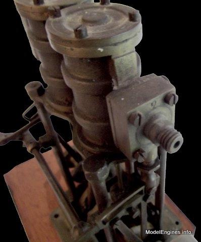
Although it had a nice patina, in that state the model looked much like a neglected (but not abused) toy. However it is much more than that, as it is a surviving example of a miniature engine which reveals the level of model engineering that existed in England well over a hundred years ago. The patina/corrosion is not so nice when you consider that it has a number of visible steel components - such as columns, crosshead guides, eccentric rods and screw heads. That portion of the "patina" is what I would call rust !
Note that steel in those times was prized above common brass. It was not readily available in rods of all sizes as it is today. It is very likely that almost all the parts of this engine, brass bronze and steel, started life as castings.
I could see the logic of "freezing this machine in time" in its present state if it were of important historical importance - such as the posession of a famous person or the prototype of a new invention. However as it represents the general type of models people made in its time, I would prefer to see it exuding its original glory like a restored automobile - not like a badly rusted car!
I tried to restore the mahogany base to a reasonable finish and colour. However I have had to shorten it due to a missing bit of wood which split off from the bottom at one end.
Time for refinishing!
At this point I was getting a "feel" for the degree of refinishing that is appropriate on this particular model and think I have hit my objective. Mostly I tried to use common sense, but have also been referring to pictures of antique models from a publication of a well-respected English auction house to confirm my thoughts. My general rule was, that where the original builder's machining marks were evident, I left them visible, but if there was evidence of rough filing marks where they actually detract from the model (or affect its working) I reduced them, but still leaving a subtle hint as evidence. I left most of the traces of tiny air bubbles in the castings - they were a fact of life in this sort of model in the era when it was constructed.
The valve chests are complete five-surface enclosures open at the back and not requiring front covers
My work to this point included no machining - only chemical cleaning. This reveals the original maker's handwork as well as various dents and scrapes acquired over the intervening years. I did chose to re-machine a few surfaces which bore these marks of distress. They would not have been present during the engine's early years.
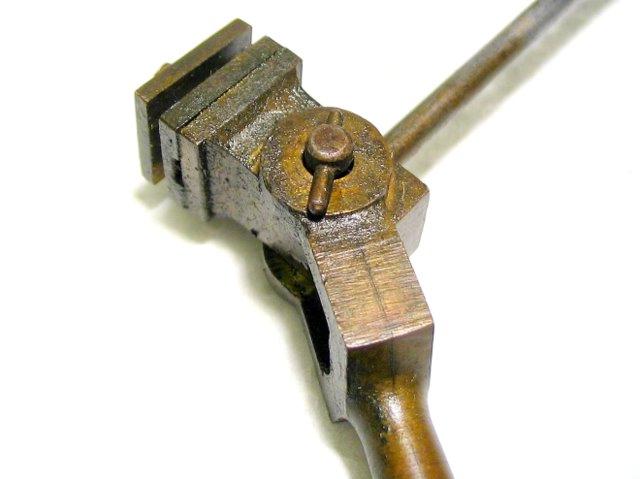
The handle is missing from the curved reversing lever - broken away at some earlier date
Digital pictures can be any colour you want (or don't)...this one shows the crank in its true silvery hue before cleaning
Here (above and below) is evidence that someone decided that the steam did not have a good path into the cylinders at the very top and bottom of the stroke - but why should it? When properly timed, some steam should already have been admitted just before dead center to provide cushioning compression.
I was conflicted about what to do about this situation. At first I wanted to make brand new pistons, but then it wouldn't really be the same engine. They were well made originally and I doubt that I could replace them with the exact brass alloy and I don't have matching number stamps in a matching font style. Another option was to try to fill the gaps by silver soldering in a filler piece and consider it a "necessary repair" but unless well done, it might lead to uneven wear on the cylinder wall if the engine were to be run at length.
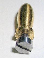
The model only required the replacement of three tiny parts - a support bushing for the reversing shaft, a small hand grip which was lost from the reversing lever, and one original steel screw which had been imitated in brass at some time during the life of the model.
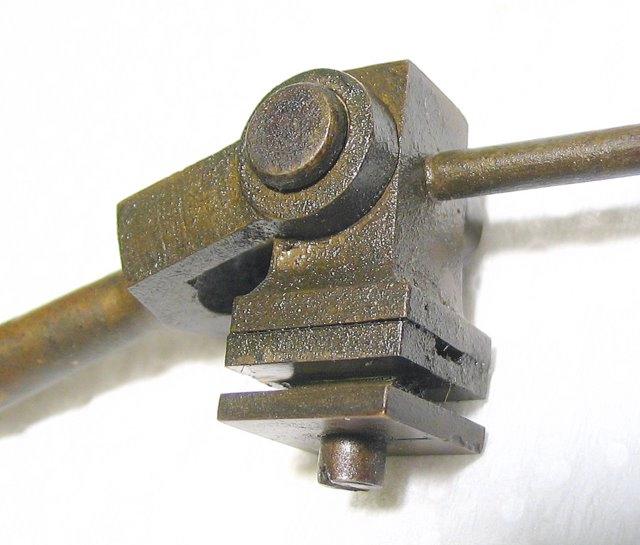
After spending so much time working on the engine I have intimate knowledge of this builder's style of workmanship. I can say without question that the bushing on the left is original and the one on the right is not. The latter is an attempt to copy the part by someone who did not have the time or perhaps the patience to duplicate this part accurately.
It was a moot point for me however since the old copied part (right) was broken at the threaded stud
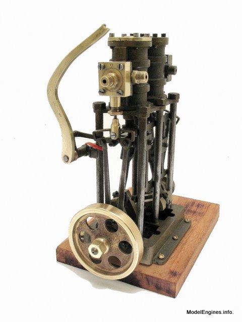
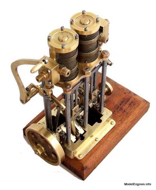
Antique Victorian Model Launch Engine
- circa 1895 -
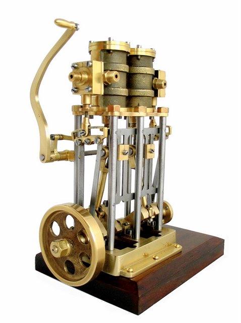
A delightful old five-column, long-stroke twin launch engine model from the North of England
In restoring this engine I have not polished it like a piece of jewellery, as that is not the way it was originally and to do that would have substantially changed the model. However it has a graceful design and was well constructed - generally in good alignment and made from attractive materials. The restored surface finish appropriately retains the 19th century builder's machining marks. The overall effect of restoration is pleasing to the eye as it reveals the beauty of this model which is into its second century of existance. The engine is most attractive on my mantlepiece - as it would also be if it were in a well made model launch.
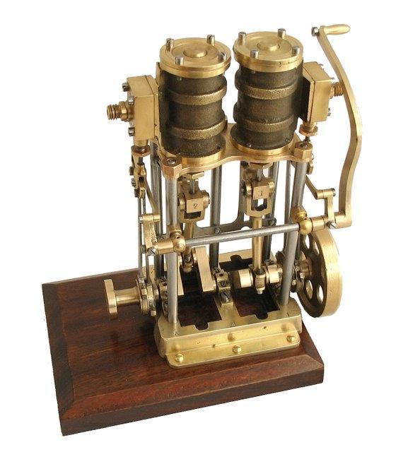
The Stephenson link reversing gear shaft and operating lever are on the open side of the engine
However this engine contains no maker's mark and I have little information other than to assume it is simply a non-factory-made steam engine constructed by someone like myself in the latter 1800's. I reached that conclusion from the style and note that it is obviously not a modern reproduction, due to the materials and methods used and all the screw threads being something other than those used for these purposes today. Many parts are made from a brass which appears to be quite different from present day versions - being quite hard and looking like German Silver (nickel brass) which was popular in old drafting instruments. There are also some gunmetal castings and steel parts as well.
It should be pointed out that much about the engine's original construction methods were almost totally obscured by the discoloration of the brass. A notable example is the existence of the machining pattern on the top surface of the main bed which were probably made by face cutting the surface in a foot-powerd lathe. These were almost certainly intentionally left visible much like the milling patterns which can be clearly seen on the tables of modern drill presses. They were all but invisible when the model was in the darkened state. Surely logic would dictate that the model be thoroughly cleaned and maintained in the condition it was in when first constructed.
This rust must be removed to prevent further corrosion of the columns and other steel parts
The engine stands 7½ inches above the wooden base and is 6 inches from the driving flange to the face of the flywheel nut.
( 1 inch x 1½ bore and stroke - flywheel diameter 2½ inches )


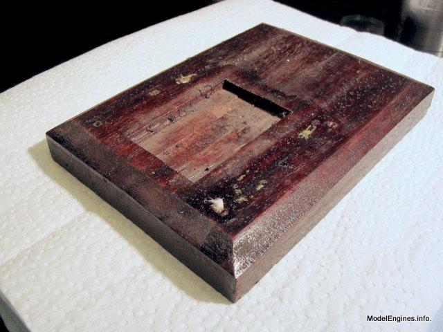
(the bottom of the base revealed it to be a worthwhile piece of wood)
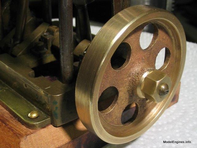
I didn't re-machine the flywheel, but chose to only brighten it chemically
in order to preserve evidence of the original machining marks
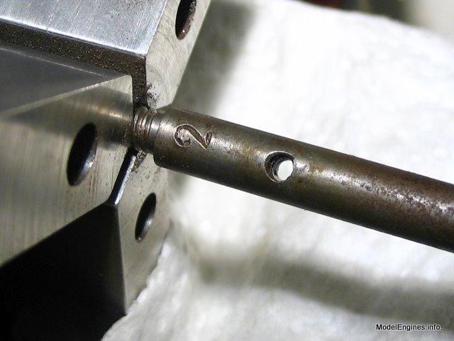
Here is one end of the soleplate clearly showing the maker's numbering,
some machining curved marks (near the"3") and a few air holes in the front of the casting

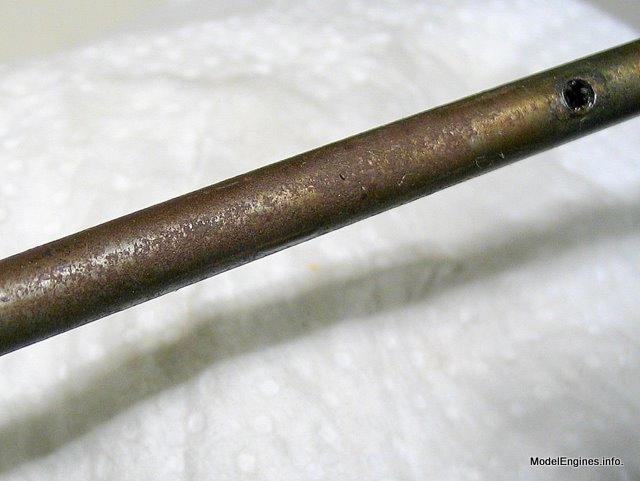
Below: an original handmade screw from the engine with the slot somewhat mangled,
presumably from many later operations with a screwdriver (including my own)

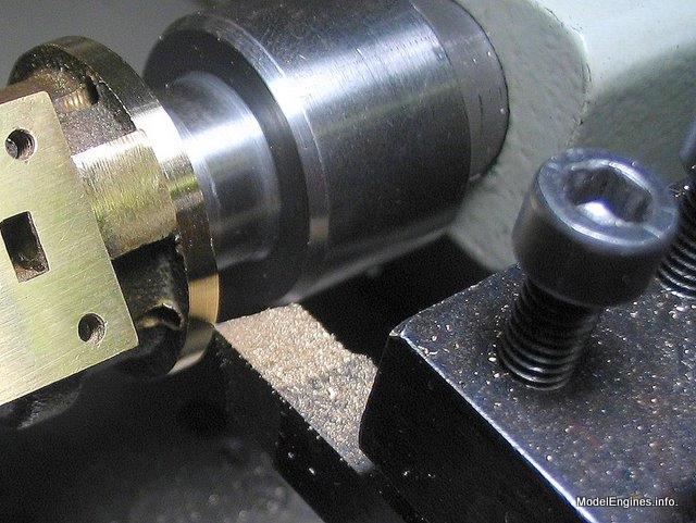
I resurfaced all the screw heads on my Taig lathe - just enough to get under the rust and the burrs on the edges of the slots
The soleplate, screws and bottom of one column after cleaning

This shows that this broken BA die matches the thread pitch of the old screws
(but not necessarily the thread form)

It is interesting to see the parts all numbered in a beautiful old typeface
The valve chest and screws after some cleaning
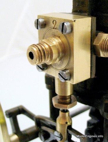
Obviously the threaded steam fitting in the front of the chest is a separate screwed-in component
Notice also that I didn't machine below the depth of every last pockmark,
to do so would have actually made some components smaller - especially screw heads.
It is clearly visible in the picture above that I must make a small hand grip from scratch
to fit on the top end of the reversing lever and do a small repair to the end of the lever.
(more about that later)
Now to the running gear

Most of the parts on this engine have been machined from castings

The eccentric straps

The bearing block in original state, but with screw slots "distressed"
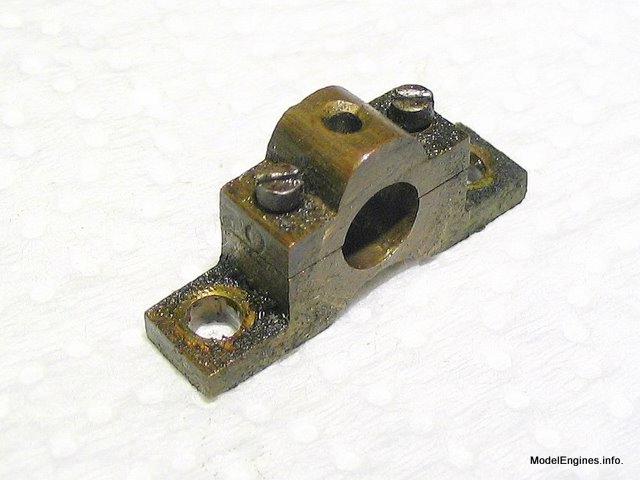
Like most of this engine a good cleaning was all that was necessary aside from re-finishing the original screw heads.

(this is very similar to the colour of my German Silver Swiss drafting instruments of similar age)


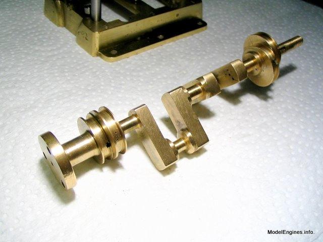
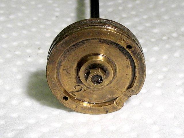
The crankshaft is integral with the four eccentrics and needed no more than a quick cleaning

The cleaned crankshaft
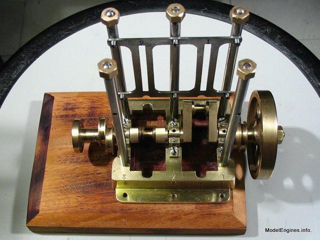
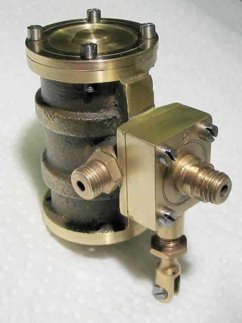
The bottom portion of the launch engine is now restored
The top of the engine
It became obvious to me after cleaning that I had to resurface the raised portions of the cylinder covers

I am doing the same here with the cylinders - machining the flanges bright to match the edges of the covers.
(taking just a skim off the surface)
The following pictures should explain it more clearly
I will allow the recesses in the top of the covers over time to gradually return to a darker colour of the unmachined cast metal
(perhaps the colour of the flywheel spoke web for now).


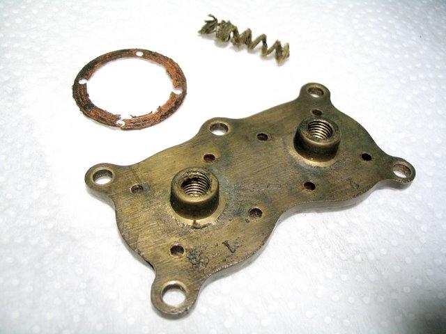
This is the combined bottom cast brass cover plate for both cylinders with an original gasket and packing
Top view of the same plate awaiting further cleaning

Part of the two cylinder bore registers in the bottom cover have been filed or ground away. Similarly, both pistons have been filed as well. This appears to have been done some time ago as the metal discoloration is the same on the cut surfaces as the rest of the surrounding metal. To me this appears to be a most illogical step as it doesn't help anything and cutting down the pistons into one of the packing gaps probably seriously compromises the piston seal in the cylinder. My suspicion is that some later owner tried the engine and found it ran slowly compared to other twins of similar size. Without acknowledging the large ratio of stroke-to-bore in this engine, the person may have simply failed to realize just how slowly it was designed to turn.
I finally decided, reluctantly, to do nothing. It is the way I received the model and it leaves all options open in the future. The engine will run OK, but it might have been slightly better if this act of mutilation had not occurred. I would like to think it was not the original model engineer who did this, but some impatient subsequent owner who held little respect for maker's work or knowledge of how steam engines work.


Obviously these next pictures were taken prior to varnishing the base

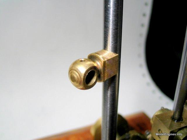
This is an original reversing shaft support bushing (the outer portion to the left)


I did my best to copy the original from Naval brass for installation on the model
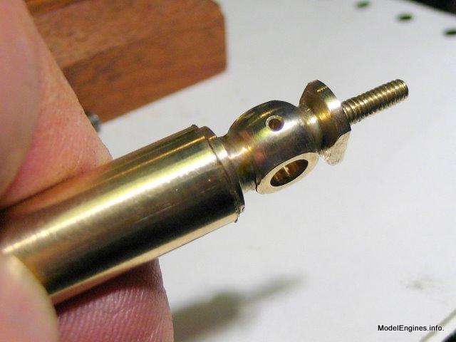
Note below that the fairing piece over the stud is original to the engine

At least it is not a glaring fake, but just a necessary replacement component.
Next job was the missing handle
This was the only piece of which I didn't have a surviving example to copy.
Some research through old engravings and ads suggested that there is a classic shape - which I used.
It was necessary to make a screw from scratch, which I matched from existing examples on the engine.

The hole in the lever was broken away, presumably causing the handle to fall off.
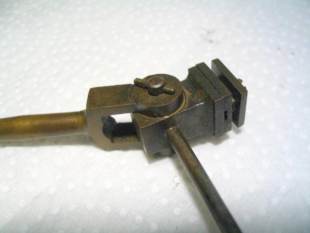
This seemed a simple way to create the missing C-shaped section

A good view showing the broken lever tip on the left
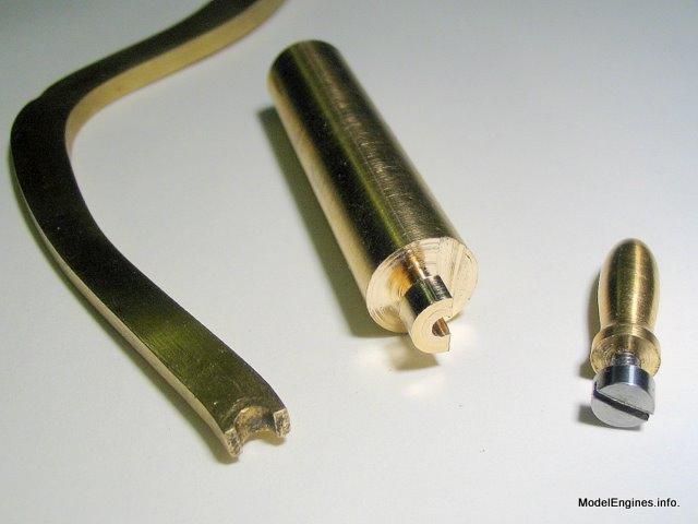
The new piece silver brazed in place before finishing work

The completed repair with the new handle attached to the lever

Well... I guess this most enjoyable job is finished!


Return to main website home page:
ModelEngines.info
![]()
© John R. Bentley 2015.